Performing Beam Excitation
Once all the checks have been performed, one can start measurements.
In the Multiturn GUI one can perform beam excitation with either the AC Dipole or the ADT, and both procedures are very similar.
Select either the ACDipole or ADTACDipole tab at the top of the GUI, depending on the desired excitation device.
Common Settings
The following settings are set identically for both the AC Dipole and the ADT, in the left-hand side of the GUI:
Kick Groups
Before exciting the beam, one should select or create a kick group. A kick group collects measurements under a single name, gathers them in the logbook and makes it easier in the future to simultaneously load related kicks at once.
Kickgroups in JSON
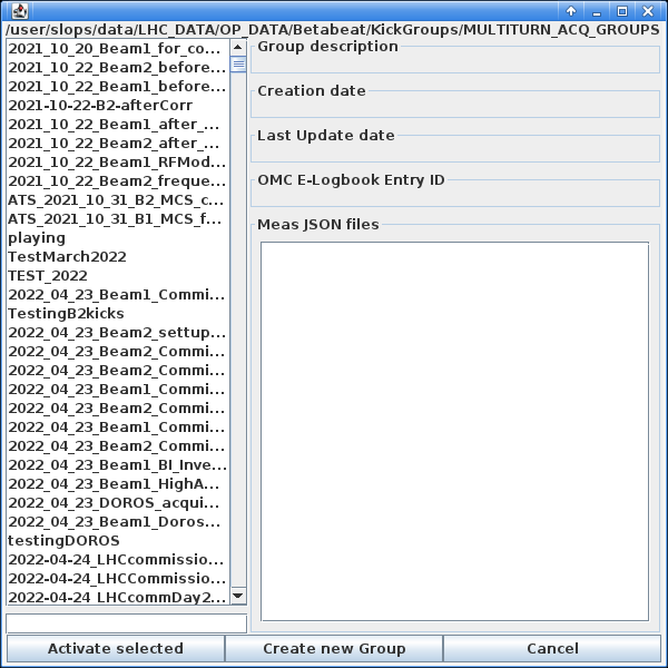
Each kick group also has a corresponding .json file in /user/slops/data/LHC_DATA/OP_DATA/Betabeat/KickGroups/MULTITURN_ACQ_GROUPS, in which the paths to the acquired turn-by-turn data and their individual .json files containing information about the excitation parameter is stored.
See also the PyLHC tool for KickGroups.
Creating a new group is done by clicking the Select Active group button in the top left corner of the GUI, which will open the following dialogue:
Typically one wants to create a new kick group. To do so:
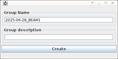
- Click the Create new Group button at the bottom in the centre, which will open the following dialogue, with a default naming scheme:
-
Adapt the text entry under
Group Nameto reflect the measurements to be done in this group. A good naming practice is to lead with the date and beam number as suggested, e.g.YYYY-MM-DD_BEAM1_Measurement_description. Make sure to pressEnterafter typing the name. Optionally add a description in the field below, and click the Create button. Once created the new group will appear at the bottom of the list of available groups. -
Select the new group and click the Activate selected. This should then create a new entry in the
LHC-OMClogbook with information about the group, and all acquisitions done in this group will be logged to that entry automatically.
Tunes Setup
The fields in this section expect the values of the horizontal and vertical tunes for the selected beam:
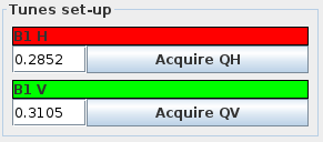
They should be the natural tunes used in the machine during measurements. Either enter the values manually or, to enter the current tunes click the Acquire QH and Acquire QV buttons which will update the value to the current one measured with the BBQ. These values can be manually refined if necessary.
Unexpected Tunes
This acquisition is also a sanity check for the state of the machine. It can happen that the machine tunes are different from what is expected, e.g. because it was forgotten to revert them to the desired working point. Such a mistake would easily be detected with a press of this button, which can prevent unexpected beam dumps. Use this feature!
Concentrator Settings
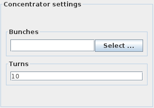
These settings refer to the excitation to be performed. The excitation device needs to know which bunches to excite and how long the excitation should last (in terms of turns).
Bunches
- To select the bunches, click the Select ... button under the
Bunchessection, which opens the following dialogue:
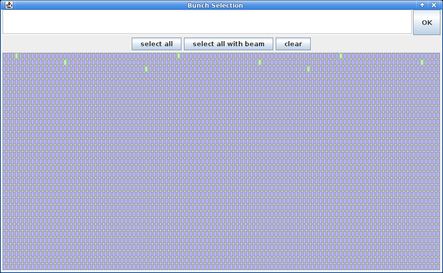
- Choose Select Bunches with Beam to select all bunches present in the machine, or individually select the bunches by clicking on their slots. This determines which bunches to record the BPM turn-by-turn data for. It is also possible to manually enter the (comma-separated) bunches to excite. Once done, click OK in the top right to validate the selection.
Turns
- Set the number of turns to maintain the excitation for in the
Turnsfield below. These correspond to the excitation plateau length, and does not include ramp-up and ramp-down times.
Excitation Duration
For AC-Dipole measurements, this setting is typically 6600 turns of flat-top excitation, while for ADT measurements it is typically 40,000 turns. Do not set these values higher than these for the respective measurements, as this can lead to the AC Dipole being damaged or the BPM buffers overflowing causing data to be lost or overwritten.
AC Dipole Excitation
Selecting the ACDipole tab will change the right-hand side of the GUI window to display the following:
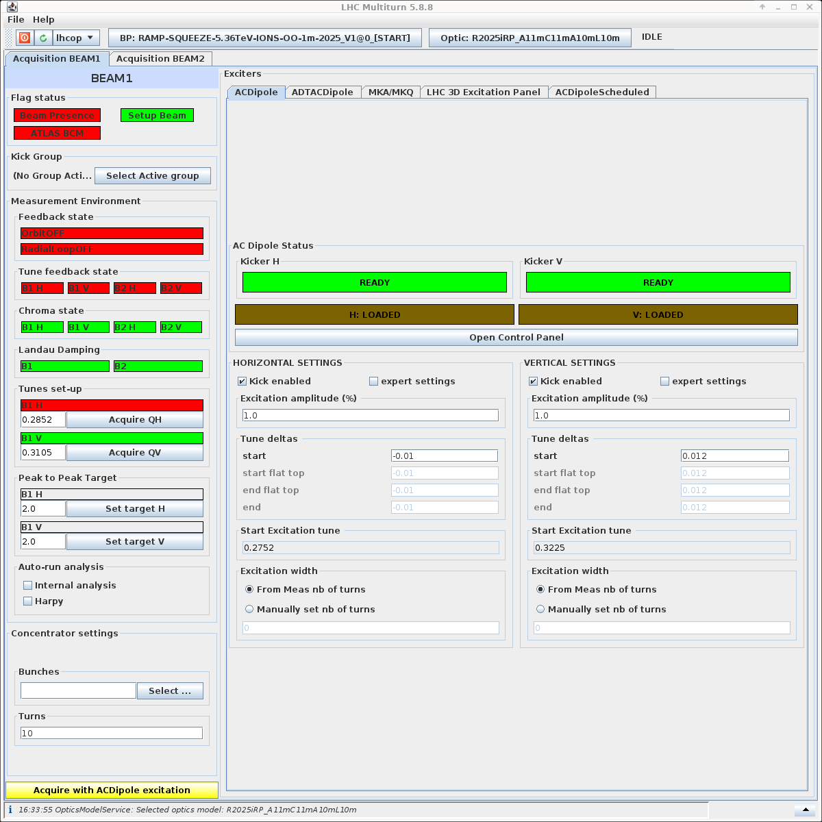
The two following settings need to be set before starting measurements.
Tune Deltas
The excitation device drives the beam motion to a different frequency than the natural tune, which is determined by its offset from the natural tune, called the "tune delta".
Set these values in the start fields of the Tune deltas section, for both the horizontal and vertical planes (Horizontal settings and Vertical settings sections).
Typical Default Values
We often perform optics measurements using the \(Q_x = 0.28\), \(Q_y = 0.31\) tunes, and the following tune deltas:
- The horizontal tune delta is typically set to \(\Delta Q_x = -0.01\).
- The vertical tune delta is typically set to \(\Delta Q_y = 0.012\).
These values result in typical excitation tunes of \(Q_x^{driven} = 0.27\) and \(Q_y^{driven} = 0.322\). Depending on the specific measurements, other tunes and tune deltas may be required. Always consult with the experts on shift if unsure about the values to use.
Diagonal Kicks
Kicking completely "diagonal", i.e. with the same absolute delta in both planes, can lead to additional resonance excitation and loss of DA. One should therefore always use slightly different tune deltas in the two planes.
The resulting driven tunes will be automatically computed and displayed under Start Excitation tune.
Make sure to double check these values, as a wrong setting can lead to a direct beam dump.
Kick Amplitudes
Kick amplitudes, together with the tune deltas, contribute to determining the excitation strength. Generally larger excitations lead to better signal-to-noise ratio and allow measuring more faint beam modes and RDTs, but come with the risk of beam losses and therefore signal degradation, or even beam dump.
Set the Kick Amplitudes by changing the value in Excitation amplitude (%) field, for both the horizontal and vertical planes (Horizontal settings and Vertical settings sections).
Always ask the experts on shift if unsure about the kick amplitudes to set.
Kick Amplitudes at Injection
As the beams have a relatively low rigidity at injection, small kick amplitudes lead to large peak to peak oscillations and we generally use small amplitudes. A reasonable starting point is anywhere between 1% and 3%, then going up slowly in steps of 2%, until beam losses during kicks stop being reasonable.
Kick Amplitudes in the Ramp
Performing kicks in the ramp requires careful planning. As the beam energy increases, so does the beam rigidity and hence larger kick amplitudes can be used. Nevertheless, careful monitoring of losses during acquisitions and adjusting the kick amplitudes accordingly is crucial.
Typically, we prepare a table of various kicks to be performed, indicating the time in the ramp, corresponding energy, phase knob setting, ATS factor, kick amplitude and optics file. These should follow the various match points for the given energy ramp programme, and the kick strengths should scale approximately linearly with the beam energy, starting from safe strength at injection.
Most of this information can be found by opening a CCM then navigating to LHC Control -> LHC Beam Control -> Settings -> LSA App Suite (or via the search).
Once the app has opened, click the Applications menu in the top left, then contexts and tick Edit types, which will open a new corresponding tab.
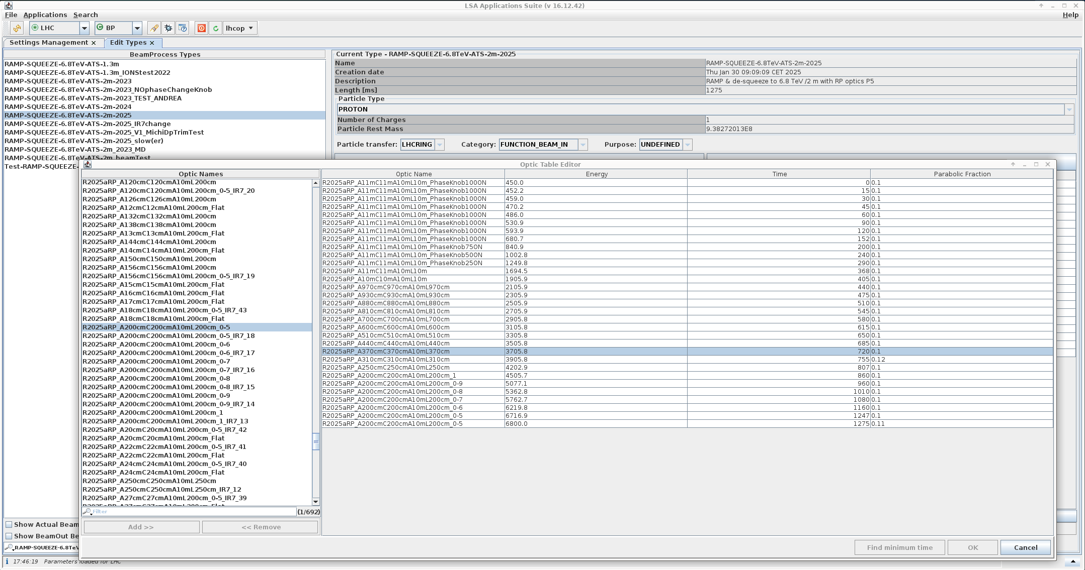
Search & select the relevant beam process using the Filter field on the left, then click the big Show optic table button on the right.
This will create a popup window displaying the match points during the ramp (if the BP is for a ramp) with their time, energy and optics file.
Missing Energy?
Should the Energy information be missing from the table, switch to the Settings Management tab (the default one), select your Beam Process, select MOMENTUM in the properties list, then the LHC/MOMENTUM variable in the rightmost list.
The graph in the lower panel will show the energy through the Beam Process, allowing to infer it at the time points from the ramp table.
An example table is shown below, generated for the proton-proton RAMP-SQUEEZE-6.8TeV-ATS-2m-2025 beam process as in the picture above.
It is okay to copy-paste a previous table and update it.
| Time | Energy (TeV) | Phase Knob | ATS | Kick Amplitude (%) | Optics |
|---|---|---|---|---|---|
| 30s | 0.46 | 100% | 1 | 3 | R2025aRP_A11mC11mA10mL10m_PhaseKnob100On |
| 240s | 1.0 | 50% | 1 | 7 | R2025aRP_A11mC11mA10mL10m_PhaseKnob50On |
| 405s | 1.9 | 0% | 1 | 13 | R2025aRP_A11mC11mA10mL10m |
| 580s | 2.9 | 0% | 1 | 19 | R2025aRP_A700cmmC700cmA10mL700cm |
| 720s | 3.7 | 0% | 1 | 24 | R2025aRP_A370cmmC370cmA10mL370cm |
| 860s | 4.5 | 0% | 1 | 30 | R2025aRP_A200cmmC200cmA10mL200cm_1 |
| 1010s | 5.5 | 0% | 0.8 | 36 | R2025aRP_A200cmmC200cmA10mL200cm_0-8 |
| 1160s | 6.2 | 0% | 0.6 | 41 | R2025aRP_A200cmmC200cmA10mL200cm_0-6 |
| 1247s | 6.7 | 0% | 0.5 | 45 | R2025aRP_A200cmmC200cmA10mL200cm_0-5 |
The values in this table are a good starting point, but it is important to monitor the losses and reduce the kick amplitudes accordingly.
Kick Amplitudes at Top Energy
At top energy the increased beam rigidity allows us larger kick amplitudes. A reasonable starting point is 5%, then going up in steps of 5% until beam losses during kicks stop being reasonable. Remember that it is very time-consuming to get back to this state when losing the beam at top energy, so monitor beam losses carefully and be reasonable with the kick increases.
Exciting the Beam
Trigger an acquisition by clicking the yellow Acquire with ACDipole excitation button at the bottom left of the GUI. The AC Dipole will arm, then kick the beam.
Watch for Losses on Kicks
Make sure to have a BLM Fixed Display application open and to monitor the losses right after clicking to acquire, and watch out for large losses and spikes close to thresholds.
This is especially important to do when increasing the kick amplitude between kicks.
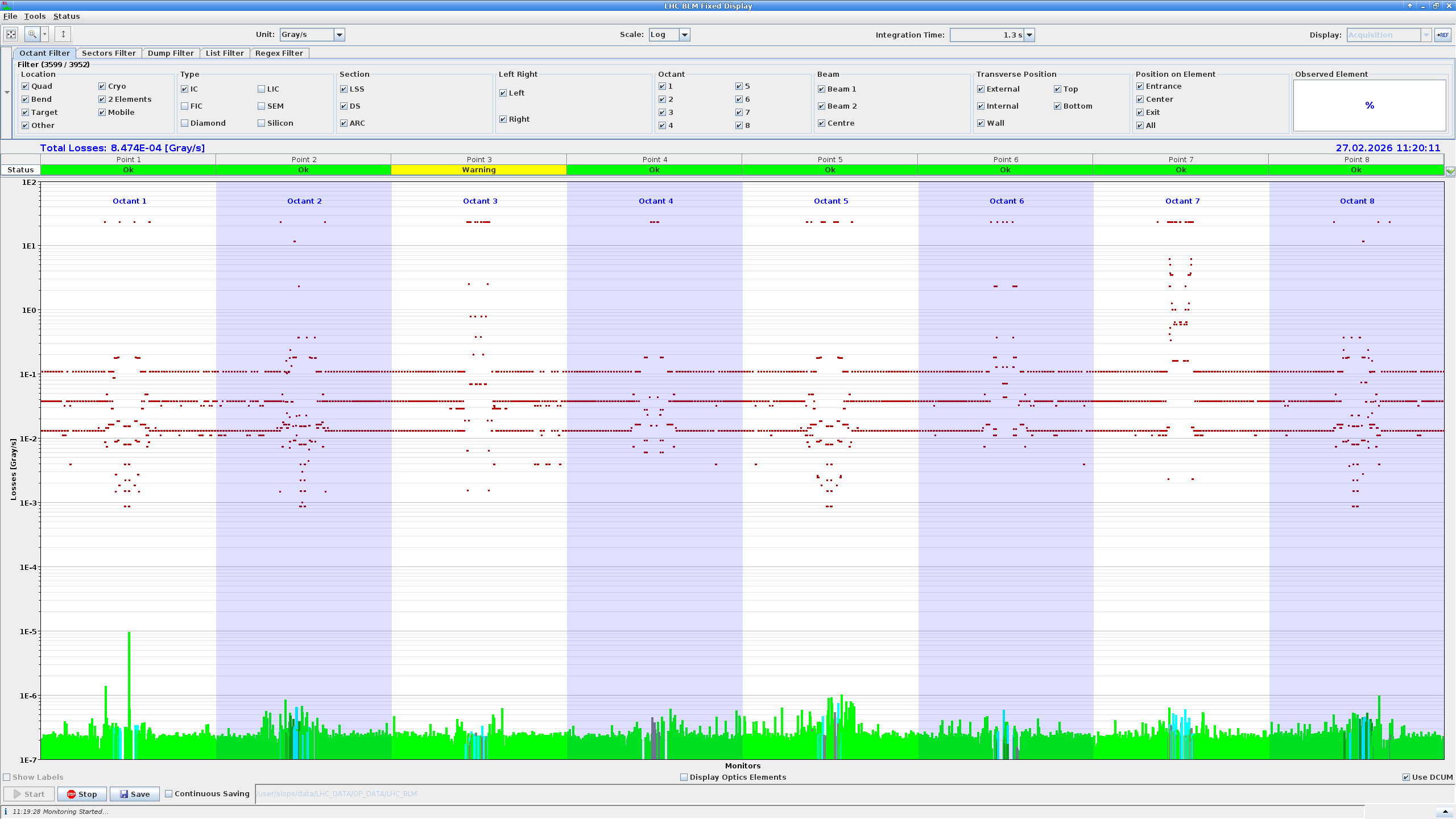
Note the log scale of the registered losses in the default view. In that GUI, the red point indicate the losses thresholds that would trigger a dump in this location. In case large losses are observed, it is recommended to kick a couple times at the current amplitude or just below to see if the losses reduce or are consistent. While doing so, also keep an eye on the beam intensity as can be seen on the vistars.
Should losses reduce, the beam might have just needed cleaning and one can increase the kick amplitude further. Otherwise stop increasing unless a beam dump is affordable (hint: it rarely is). Refer to the experts on shift if unsure about the losses, and whether the kick amplitude can be increased further.
After the kick is done, a new tab will open at the very top of the GUI to display the BPM measurements, which can be checked: a menu list lets one select any BPM from each beam, and view the recorded bunch centroid turn-by-turn data through the acquisition.
Do not Kick Both Beams Simultaneously
Firstly, kicking both beams simultaneously might exceed the losses threshold and lead to a beam dump.
Secondly, triggering an acquisition will always turn off the tune feedback, radial loop, and orbit feedback for that beam. Afterward, the system restores these to the exact state they were in before the acquisition. This means if one kicks Beam 1 and quickly after Beam 2, Beam 1’s feedback loops will be left off! This is because they were off when the system triggered the Beam 2 measurement, and the system restores the global state.
As a rule of thumb, wait a few seconds in between kicking the two beams.
ADT AC-Dipole Excitation
Selecting the ADTACDipole tab will change the right-hand side of the GUI window to display the following:
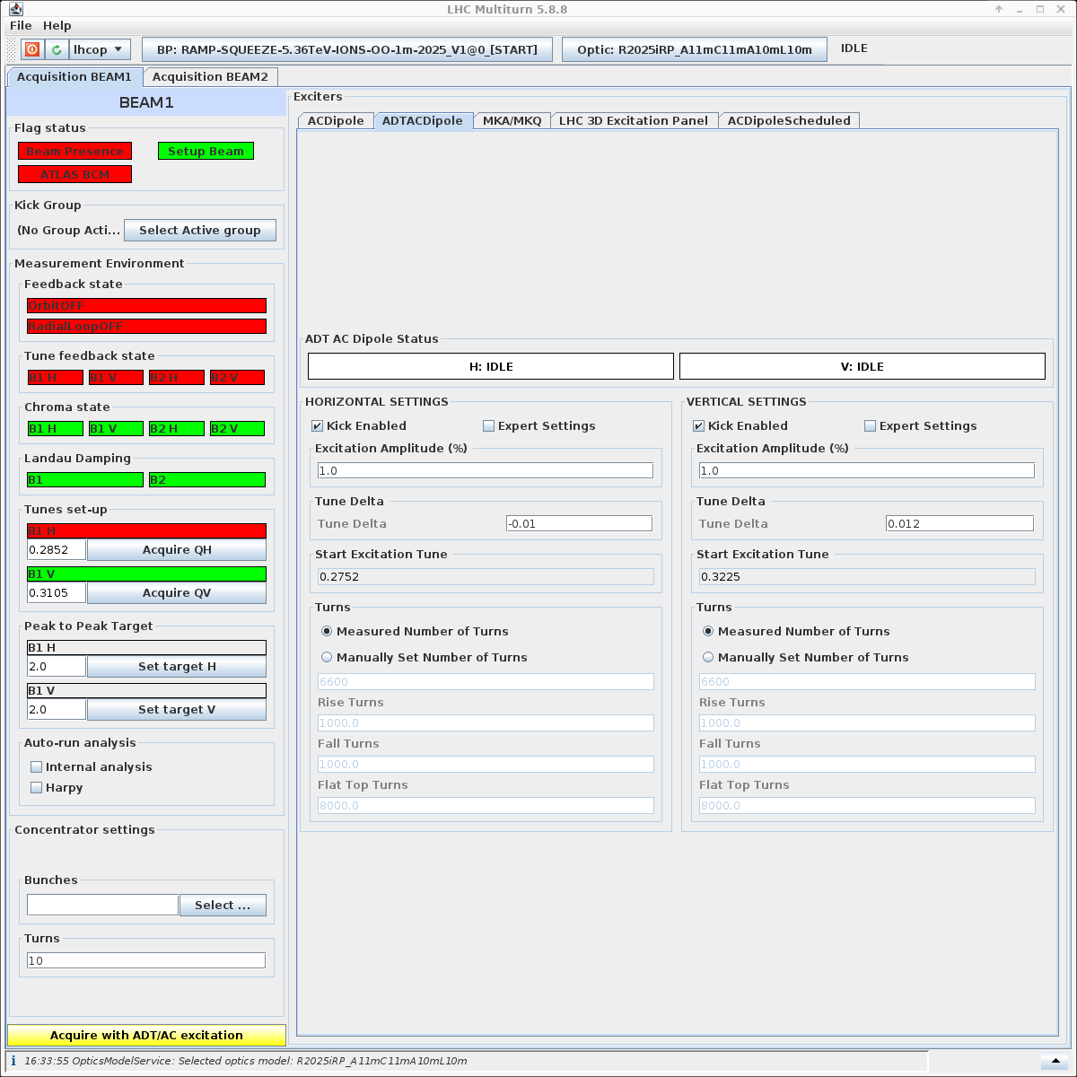
Currently ADT AC-dipole measurements are almost identical to the AC Dipole measurements, but due to the limitations of the magnet, cannot (yet) reach the same kick-strengths as the dedicated AC-dipole. This deficit can be overcome in improving the signal-to-noise ratio through increased measurement lengths, i.e. up to 40,000 turns. Refer to the AC Dipole Excitation section above for the settings and steps.
Kick Amplitudes
When used in coupling mode, a maximum kick amplitude of 30% can be used, although this depends on the working point and tune deltas used. It is recommended to start around 10% and go up in small steps while watching the losses. In any other configuration, please refer to the EIC on shift.
Trigger an acquisition by clicking the yellow Acquire with ADT/AC excitation button at the bottom left of the GUI.
Just as with the AC Dipole, make sure to keep an eye on the losses (via the BLM Fixed Display and beam intensities) during the acquisition.