Safety Checks
After selecting which beam to excite and acquire data for, the next step is to prepare the correct excitation settings and check for various state flags. A first check to perform is that specific systems of the machine themselves are in the correct state to allow for beam excitation. Some general checks are available on this page, and below are the specific checks to perform in the Multiturn GUI.
Good Red, Bad Red
As one will see below, an indicator coloured in red is not always a bad thing in the Multiturn GUI, due to conventions. Check thoroughly the meaning of each indicator (also called flag) from the instructions below and make sure they are in a correct state.
Quick Recap
Please read the following sections carefully regarding the meaning of various flags. Here is a quick recap of flags to check and the expected state for measurements:
| Flag | Expected State | Notes |
|---|---|---|
| Beam Presence | Green | Beam must be present. |
| Setup Beam | Green | Beam must be in Setup mode. |
| ATLAS BCM | Red | Should be masked (red). Ask EIC to contact ATLAS control room to mask BCM. |
| Orbit Feedback | Red | Orbit feedback should be off during measurements. Turned on/off automatically |
| Radial Loop | Red | Radial loop feedback should be off during measurements. Turned on/off automatically |
| Tune Feedbacks | Red | All tune feedbacks should be off during measurements. Turned off/on automatically. |
| Chroma Feedback | Green | Displays acceptable (or not) state of last measured chromaticity value. |
| Landau Feedback | Red or green | MOs usually off, unless you want to include their effect in the measurements. |
Flag Status
At the top left of the GUI, a small section titled Flag Status displays simple main flags, as shown below:
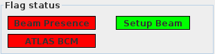
Their meanings are as follows:
Beam Presence: indicates whether beam is circulating in the LHC, for the beam corresponding to the selected tab. This will be green if beam is present, red otherwise. Always make sure it is green.Setup Beam: indicates whether the beam status set by the operator isSetup. It will be green if the beam is inSetupmode, red otherwise. Always make sure it is green.ATLAS BCM: indicates whether the ATLAS BCM has been masked from the interlock. It is green if the ATLAS BCM is active, red otherwise. Always make sure it is red, as we measure in special beam conditions and want it to be masked.
Masking the BCM
The ATLAS BCM can only be masked by ATLAS operators, from their control room. Ask the current EIC to call the ATLAS control room and ask to mask their BCM before starting measurements.
Measurement Environment
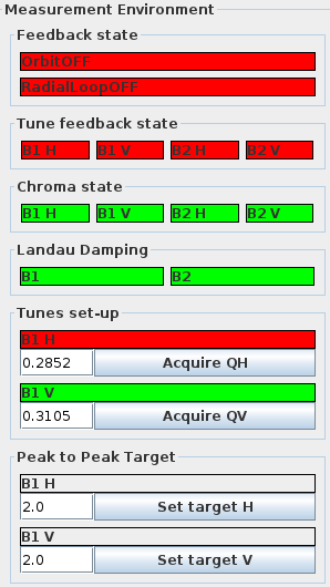
The Measurement Environment section just below provides a quick overview of the current machine feedback and damping states, as can be seen below:
Feedback State
OrbitOFF(red) indicates that the orbit feedback is currently off and will appear green and change toOrbitONwhen it is active.RadialLoopOFF(red) shows the radial loop feedback is off; when on, it will appear green asRadialLoopON.
What are those?
The orbit feedback acts on correctors to keep the measured closed orbit to the reference one. The radial loop feedback acts on the RF cavities to keep the beam's bunched in the centre of their respective RF buckets.
Both these feedback systems should be off during measurements, but on between kicks. They will automatically be turned off when you start a measurement, and will be turned back on as soon as the acquisition is complete.
Tune Feedback State
These buttons represent the state of the tune feedback for each beam and plane:
B1 H: Beam 1, HorizontalB1 V: Beam 1, VerticalB2 H: Beam 2, HorizontalB2 V: Beam 2, Vertical
Red indicates the feedback is off, green indicates it is on.
What are those?
The tune feedback acts on dedicated quadrupole circuits in the arcs to keep the beam's tunes to the desired values.
These feedback should be off during measurements, but on between kicks. They will automatically be turned off when you start a measurement, and will be turned back on as soon as the acquisition is complete.
Chroma State & Landau Damping
Similarly to the above, these flags display the state of the chromaticity for each beam and plane (for chroma state), or simply each beam (for landau damping).
Chroma State: indicates the status of the last measured chromaticity value; displays as green if acceptable for optics measurements and red otherwise. Always make sure it is green.Landau Damping: refers to the powering of the MO circuits and is red when the MOs are off, green when they are powered. It should usually be red, but can be green should you choose to include the effects of the MOs in your measurements.
Talk to the experts on shift if you are unsure about these settings.
What are those?
The chromaticity state is a simple check on the beam's chromaticities vs acceptable values. The Landau damping flags display the powering state of the octupole circuits in the arcs, which are used to damp the beam's coherent oscillations.
Kicker Keys
In order to allow for beam excitation with the AC Dipole or the ADT, the physical key must be inserted in the nearby server room, and turned to correct setting. Let the current EIC know which device you plan on using, and ask them to go insert the key in the server room.
When all these checks are satisfied, proceed to the next step of the measurement setup.